SkateArm v0.8 · sim-first today · the real R.Botic Skate is en route
Open robotics · ROS 2 · MuJoCo

Drive a two-armed robot
from your browser.

SkateArm is an open browser cockpit and ROS 2 / MuJoCo toolkit for the R.Botic Skate — a 3D digital twin you actually drive, over the same wire the real robot speaks.

No robot required to try it. Everything here runs in simulation today; one switch is wired for the real Skate when the hardware lands.

16 arm DoF · 8/arm RRT-Connect MIT
Skate Commander · live twin
60 Hzcontrol loop
20 HzUI telemetry
0.3 sdeadman heartbeat
<1 µmFK vs MuJoCo
CI test status badge MIT license badge GitHub stars badge Works with ROS 2 MuJoCo URDF / MJCF Python
What the cockpit does

A robotics workstation, in a browser tab.

Every command goes through the same safe bridge the real robot will use — joint limits, a collision guard and a deadman E-STOP — whether you're jogging a slider or replaying a program.

01

Two arms, one command.

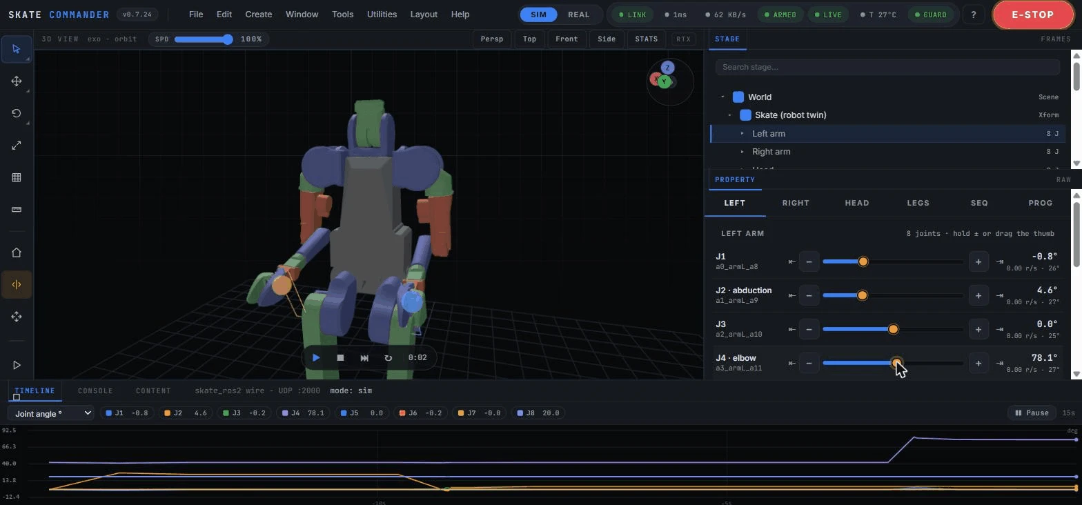
Grab a wrist in 3D and server-side damped-least-squares IK glides the seven arm joints (the eighth is the gripper), resolving the redundant freedom toward a natural pose. Turn on mirror mode and one slider drives both arms symmetrically; dual-arm carry holds one object with both wrists and moves them together.

drag-IK · mirror · CARRY · acceleration-limited glides
dual-arm carry
02

It plans around itself — and asks first.

When a straight move would clip a self-collision, RRT-Connect routes the arms around it. Risky moves — Home, waypoints and smart-pick — preview as a translucent ghost robot with a route trail, gated behind Approve / Cancel before they run.

RRT-Connect · ghost preview · path-checked guard · contact reflex
ghost preview + approve
03

See everything, live.

Foxglove-style telemetry strip charts (angle / velocity / temperature / TCP) at 20 Hz, an RViz-style live TF frame tree, a diagnostics panel and joint-limit meters — the whole robot state, readable at a glance.

strip charts · TF tree · diagnostics · CSV export
live telemetry
Live telemetry strip charts under the 3D view
The differentiator

The cockpit is the product.

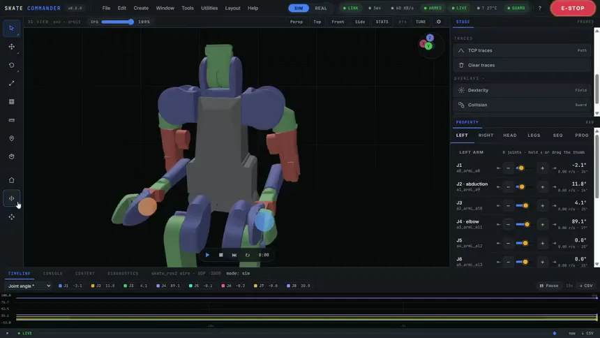
An Isaac-Sim-style workstation — menu bar, tool rail, a 3D MuJoCo twin, a Stage / Property dock and a timeline — running entirely in your browser over a WebSocket. No ROS, no Gazebo, no Linux to install just to look.
  • Where RViz, Foxglove or the MuJoCo viewer only show robot state, this cockpit drives it.
  • Built from the official URDF; FK matches MuJoCo link positions to under a micron.
  • Starts E-stopped, arms at the robot's measured pose; the firmware's 0.3 s deadman watchdog dampens the arms if the heartbeat stops.
  • Python programs + teach-in: move the arms by hand, it writes the code.
Skate Commander v0.8
The Skate Commander cockpit: menu bar, tool rail, 3D twin, Stage and Property dock, timeline
How it works

One protocol, sim and real.

The cockpit and your ROS 2 stack both speak the Skate's native UDP wire. Develop against the MuJoCo twin today; swap 127.0.0.1 for r.local when the robot arrives.

Skate Commander browser cockpit Your ROS 2 stack skate_ros2 driver SkateLink native UDP wire MuJoCo twin sim endpoint · today Real R.Botic Skate when hardware lands commands ⇅ telemetry 60 Hz
Try it · no install

Runnable examples.

Open the cockpit (it runs on recorded telemetry) and read the source behind each capability. Grab a joint slider, jog, or press Home to drive the twin yourself.
Mirror mode drives both arms from one slider in the cockpit

Drag-IK & mirror

Glide a wrist in 3D; mirror both arms from one input.

The cockpit drives an arm along an RRT-planned path that routes around a self-collision

Plan around collisions

RRT-Connect routes around self-collisions; ghost-preview gates the move.
Live telemetry strip charts and a TF frame tree under the 3D view

Live telemetry & TF

20 Hz strip charts, an RViz-style TF frame tree, diagnostics.

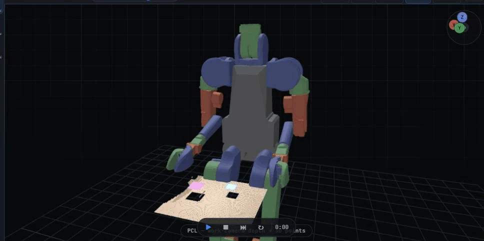
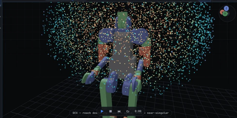
A colour-coded manipulability cloud of the arm's reachable workspace

Manipulability cloud

A DEX cloud of the reachable workspace, coloured by dexterity.

A depth point cloud of the scene with a synthesized top-down grasp

Point cloud & smart-pick

Depth back-projected to a cloud; top-down grasp synthesis. (sim-validated)
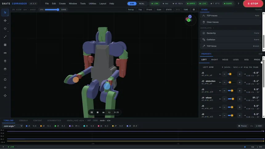
Teaching a program by moving the arms by hand in the cockpit

Teach-in programs

Move the arms by hand; the cockpit writes the rbt program.

The stack

Sim-first, wire-honest.

Four open layers, each shipped as a standalone tool. Build the whole thing in simulation, then deploy over the same protocol.

Layer 01

Sim foundations

Control-ready MuJoCo model + a capsule collision layer; kinematics validated against MuJoCo link positions.

Layer 02

skate_ros2 — the wire

A ROS 2 driver over the native UDP protocol + a protocol-true MuJoCo sim endpoint, with a deadman watchdog.

Layer 03

Skate Commander

The browser cockpit: server-side IK + collision guard, RRT routing, planning previews, live telemetry, a TF tree.

Layer 04

Autonomous work-cell

A GRAFCET-sequenced two-handed assembly cycle with camera quality inspection and a SCADA dashboard.

Phase 1 — the autonomous cell, end to end.

One arm fixtures a base part in the air; the other aligns a peg by relative servoing and inserts it with a force-guarded descent. A GRAFCET sequencer runs the cycle on sensor transitions; two fixed cameras deliver the accept / reject verdict, logged to a Flask + SQLite dashboard. Numbers below are from logged sim cycles.

42.6 scycle (takt ≤ 60 s)
±1.6 mmQC alignment
±3.4 mminsert depth
bimanual work-cell · twin
Manipulation core · contact-force control

It measures what it touches.

Phase 1 guarded contact with an actuator-torque watchdog — push until a number trips. The manipulation core replaces that with a real wrist wrench and closed-loop force control: an insertion that searches for the bore, an arm that yields at a commanded stiffness, and a gripper that holds by friction instead of a weld. All four milestones are shipped, and each one is exercised by CI.

  • M1 — wrist force/torque sensing. A 6-axis contact wrench at each wrist flange, checked against a known static load to < 0.05 N. It replaces the sum-of-actuatorfrc proxy — you cannot regulate a force you cannot read.
  • M2 — force-regulated insertion. Axial admittance on the descent setpoint, plus a spiral bore search. Misalignment tolerance 6/6 at 2 and 4 mm, 5/6 at 6 mm, 3/6 at 8 mm — where the open-loop descent manages ≤ 1/6. Peak axial force stays 3.3–4.6 N against a 9 N abort, and a 9.3° peg tilt is levelled to under 2°.
  • M3 — Cartesian admittance. A virtual mass–spring–damper at the TCP: the arm yields to a contact wrench at a tunable per-axis stiffness. Over a 16× stiffness sweep the yield lands on e = F/K exactly — 40/20/10/5/2.5 mm under 8 N — and springs back to the nominal pose on release.
  • M4 — a real gripper. Parallel jaws under closed-loop grasp-force control: 2–5 N tracked to within 0.05 N, the part held by friction, not a weld, and a slip curve that scales the way friction should — a 5 N grasp carries 5.25 N before it lets go. Those jaws now run both hands of the live S0–S7 cycle on an opt-in scene with no weld active in it anywhere: the left hand picks the base off the table at 12.00 N on its own pad sensor and sets it at an assembly station (a weld held it in mid-air for free), the right closes on the peg against the same 12 N target and carries it on friction alone with 0.42 mm of slip, S4 inserts to 22.1 mm at 2.98 N, both hands open to release, and the left re-grips the finished unit to bin it — 75.8 s against the weld path's 42.6 s.
<0.05 Nwrist wrench error
6/6seated at 2–4 mm off
16×stiffness, e = F/K
5.25 Nheld before slip
M3 admittance · push and yield
An external push on the wrist makes the arm yield along the pushed axis and spring back to its nominal pose when the force is removed
M4 gripper · grasp, carry, place — no weld
Parallel jaws on the wrist close on a part, carry it over a bin and open to release it, the part held by friction throughout

Every number above is recomputed from raw data, on every push.

Each sweep writes its trials to a committed JSON file, and a test re-derives every published figure from those files — the misalignment curve, the stiffness sweep, the slip curve, the cycle time. It runs in the hardware-free CI job with no MuJoCo and no GPU, so prose and data cannot drift apart silently: change a number in the text without changing the measurement and the build goes red.

22checks in CI
9raw data files
0hand-typed stats

The last weld, removed — and what it turned out to be holding.

Taking the weld off the second hand is not a re-skin of the same cycle. A weld holds the base in mid-air for free while the peg goes in; jaws have to pick it off the table, set it down, let go, and pick the finished unit back up — four real grip/release operations on the left hand and two on the right, each one reported by a pad force sensor, with both weld constraints sampled three times across the cycle and never once engaged. That is where the extra 33 s goes: the takt bound moves 60 s → 85 s, and the test writes down which step spent each second of it rather than letting the bound absorb it unexplained. In simulation, and on an opt-in scene: the default cell keeps its welds, and the only thing the station lens added to it is one <camera> line — no size changes, and the model steps bit-identically — so every other demo, log and benchmark on this page still reproduces exactly as it did before.
22.1 mminsert at 2.98 N
0.43 mmre-grip drift
75.8 scycle (takt ≤ 85 s)
weld-free cell · S3 align → S4 insert
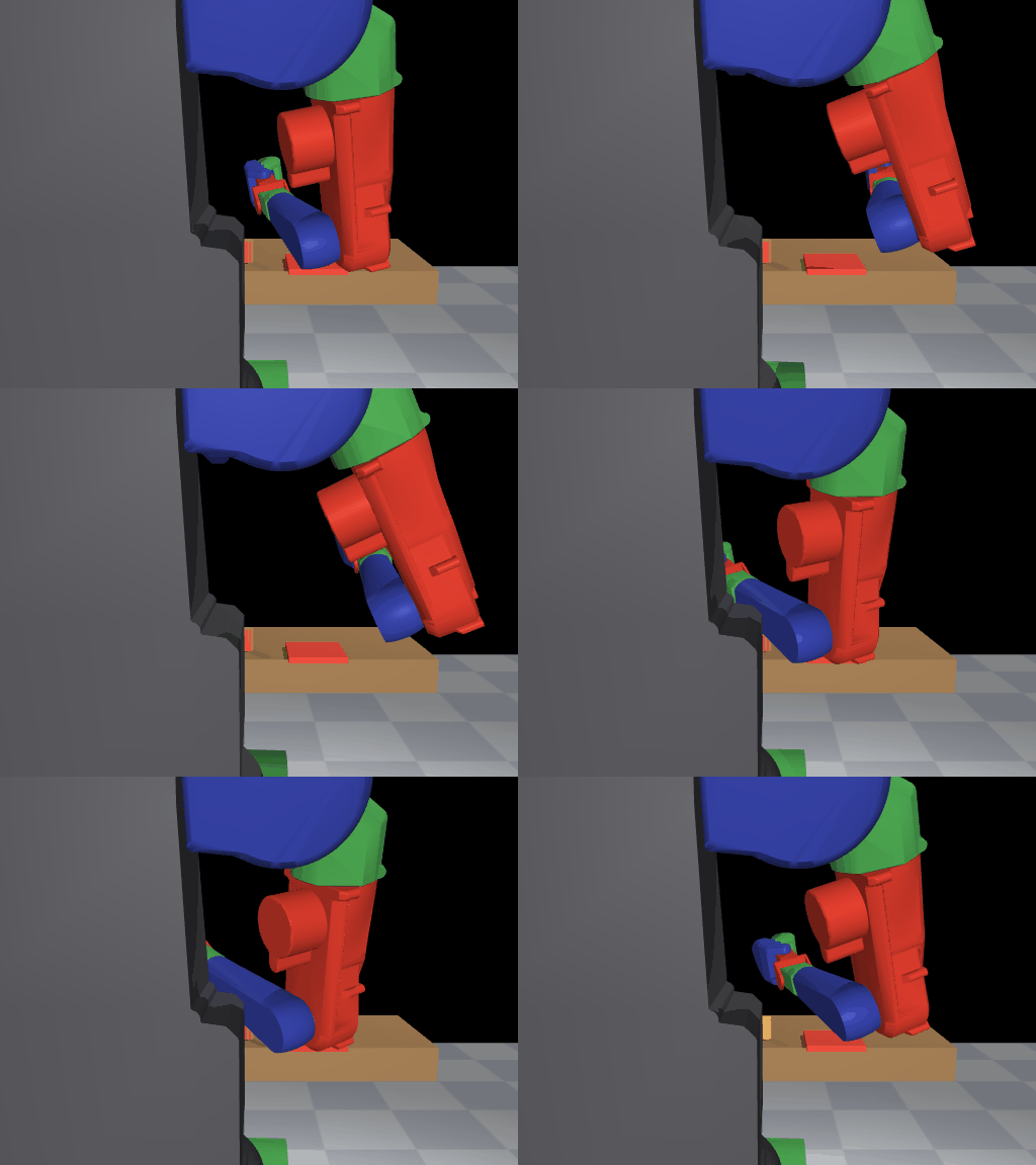
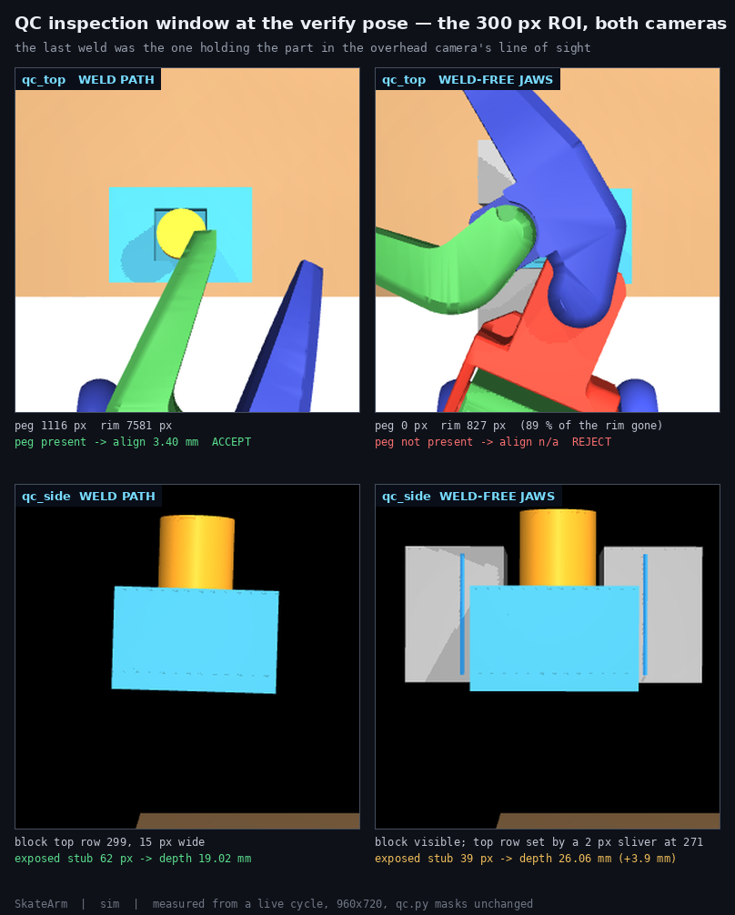
QC inspection window · weld path vs weld-free
The 300 pixel QC inspection window on both paths: the weld path shows the peg and the pocket rim, the weld-free path shows the left tool blocking the view

It cost the camera gate. That is worth more than hiding it.

With jaws on both wrists the left tool must approach top-down — the pocket faces up and the part is longer than the jaws open, so the orientation is forced — which parks the wrist between the overhead camera and the unit at exactly the pose inspection looks at. In the same 300 px window, unchanged pipeline: the weld path sees 1116 peg pixels and ACCEPTs; the weld-free path sees zero, with 89 % of the pocket rim gone, and REJECTs. Same probe on both, so the cell changed and not the measurement — and the two cells settle the part 7.7 mm apart, 16 px of that 300 px window, published next to the counts so you can rule that out yourself instead of taking “same probe” on trust. The pose oracle accepts the unit on both paths: what the conversion cost is the sight of the part, not the assembly. The published fixture-camera numbers stay on the weld path where they were earned — and the repair this page named, in-situ optics aimed at the assembly station rather than a re-calibration, has since shipped. S5 hands the unit over in an instant when the right wrist has already retracted and the left has not yet re-gripped: the part stands free on the station with both hands off it, an instant a cell with a weld in it cannot have, because it lets go of the part only onto the weld. Read there through the same unchanged pipeline, the station pair sees 956 peg pixels and ACCEPTs, the pose oracle agrees on that same frame, and the weld-free cycle is camera-gated on its own cell.

1116 → 0peg px in window
−89 %pocket rim seen
ACCEPTon the sim oracle
Learning · imitation

From cockpit to a trained policy.

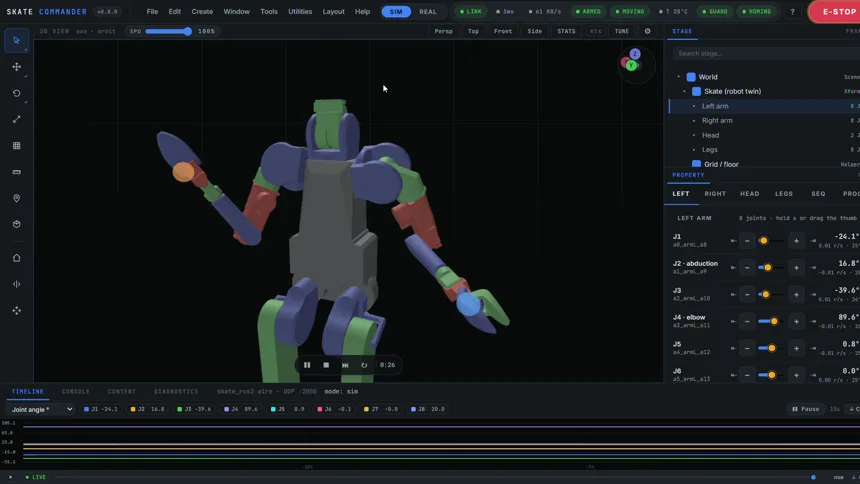
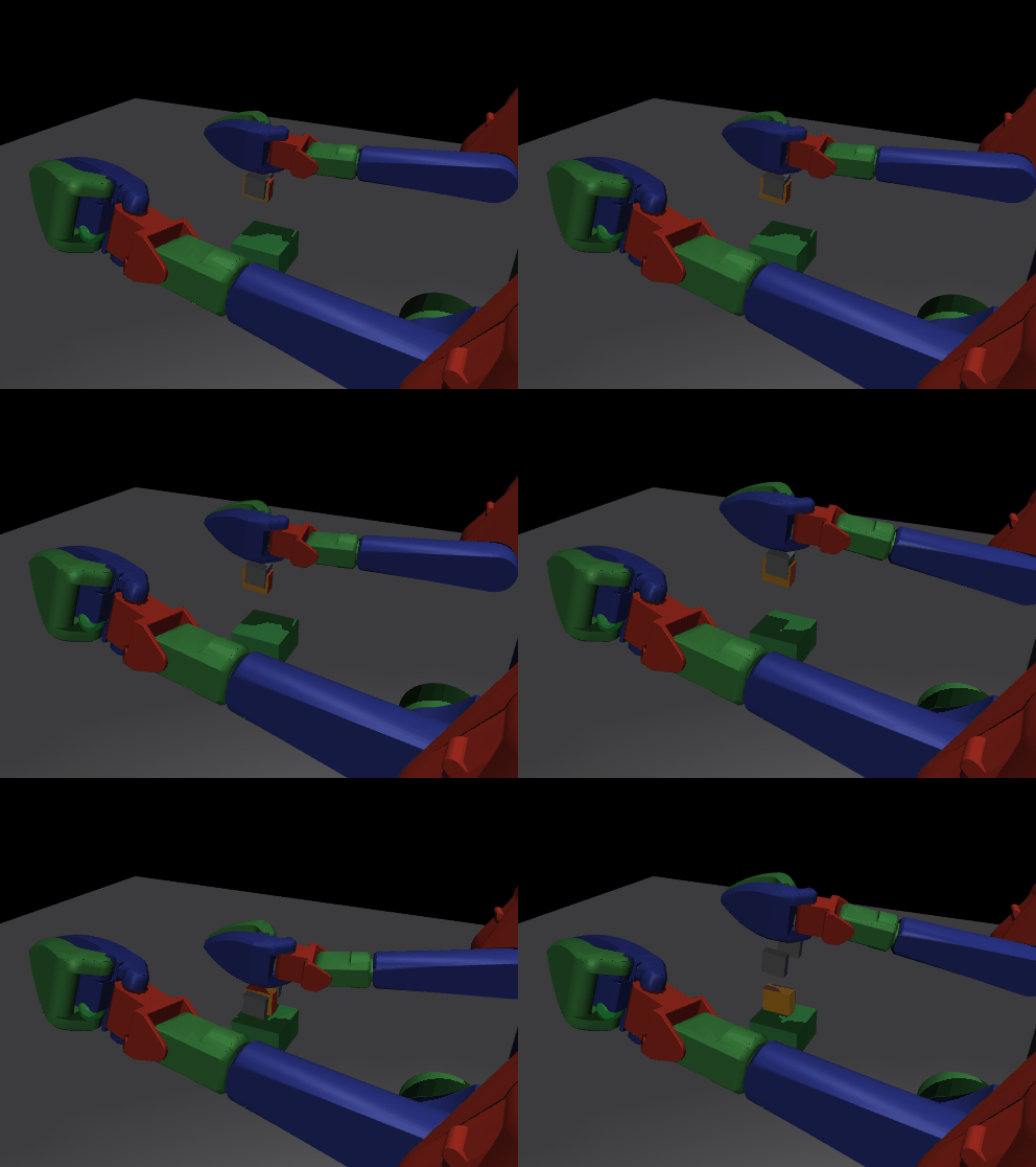
The same twin you drive also generates training data. A scripted expert demonstrates bimanual reaches; an ACT policy is behaviour-cloned from them and drives both arms from pixels alone — end to end on a single 4 GB laptop GPU.
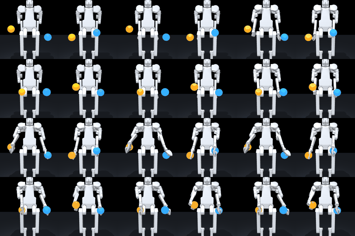
  • A scripted DLS-IK expert glides both arms to random targets, exported as a LeRobotDataset v3.0 (40 episodes).
  • An ACT policy (ResNet-18 + Transformer, 52 M params) is behaviour-cloned from the demos — trained in ~32 min on a laptop RTX 3050.
  • Rolled out closed-loop, it reaches targets it only ever sees — handed the camera frame + joint angles, never the coordinates.
  • Honest scope: in-distribution eval, single seed — a working pipeline end to end, not a benchmark.
~5 cmmean reach error
52 Mtrainable params
~32 minon an RTX 3050
ACT rollout · reaching from pixels
A trained ACT policy driving both arms to orange and blue targets in the MuJoCo twin from the camera view alone
Questions

Honest answers.

Do I need the robot to try this?
No. Everything runs in simulation today — the cockpit drives a MuJoCo digital twin, and the ROS 2 driver talks to a protocol-true sim endpoint. The real Skate is en route; nothing here claims real-hardware performance yet.
How is this different from RViz, Foxglove or the MuJoCo viewer?
Those visualise. SkateArm drives — it's a control cockpit with server-side IK, a collision guard, RRT routing, planning previews and teach-in, talking the robot's real UDP wire. And it runs in a browser tab with no install, where those tools need a Linux + ROS setup.
Does it work with my ROS 2 / MuJoCo setup?
skate_ros2 is a standard ROS 2 package speaking the documented UDP protocol, with a MuJoCo sim endpoint on the same wire. Models are plain URDF / MJCF. The wire, kinematics and command sandbox ship with unit tests that run without ROS or a robot, exercised by CI on every push.
Is it really open source?
Yes — MIT licensed, on GitHub, with CI and a contributing guide; issues and pull requests are welcome. The skt_v3 model belongs to R.Botic and is not redistributed.
What's the path from sim to the real robot?
The cockpit and the ROS 2 driver already speak the Skate's documented UDP wire; the sim endpoint and the firmware share the same protocol, deadman and 26-DoF joint ordering (16 of them in the two arms). The path is built but not yet hardware-verified — when the robot arrives you swap the host address. Phase 2 is hardware bring-up.

Drive it in your browser.

No install — the cockpit runs against baked telemetry, and you can jog the joints yourself. The source, the wire and the work-cell are all open.